- Product description
-
Product descriptionMKS 110 = medium-duty cable tray system with a side height of 110 mm.
Magnetic shield insulation without cover 20 dB, with cover 50 dB.
-
- Technical data
-
Technical data
Colour zinc Connector version Without connectors CO₂ Footprint (GWP) Cradle-to-Gate 8,198 kg CO₂e / 1 Meter Dimension 110x200x3000 Dimension B 200 mm Height 4 in Height 110 mm Length 10 ft Length 3000 mm Load test type according to IEC 61537 Type II Maintain electrical functions no Material Steel Mounting perforation in base yes NATO hole pattern no Plate thickness 0,04 in Plate thickness 1 mm Rustproof steel, pickled no Side perforation yes Support spacing 1.5 m 1,85 kN/m Support spacing 2.0 m 1,3 kN/m Support spacing 2.5 m 0,75 kN/m Support spacing 3.0 m 0,6 kN/m Surface Hot-dip galvanised Type of connector, cable support system Screwed Usable cross-section 22000 mm² Usable cross-section 220 cm² Wide-span version no Width 8 in Width 200 mm With cover no Technical data
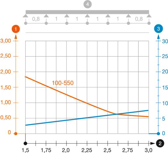
Load diagram, cable tray, type MKS 110
-
 Permitted cable tray/ladder load in kN/m without man load
-
 Support width in m
-
 Rail bend in mm at permitted kN/m
-
 Load scheme during testing
-
 Load curve with cable tray/ladder width in mm
-
 Strut bend curve according to support width
-
- All types
-
All types
- Downloads
-
Data sheet MKS 120 FT / 6060625 , 0.56MB , pdfEU declaration of conformity MKS 120 FT / 6060625 , 0.10MB , pdfUK Declaration of Conformity MKS 120 FT / 6060625 , 0.09MB , pdfREACH Declaration of conformity MKS 120 FT / 6060625 , 0.12MB , pdfRoHS Declaration of conformity MKS 120 FT / 6060625 , 0.12MB , pdfEnvironmental declaration Umweltproduktdeklaration (EPD) , 1.48MB , pdfMounting instructions Schraubbare Kabelrinnen mit Formteilen zum Schrauben und Klemmen , 5.42MB , pdfMounting instructions General information on the mounting , 2.61MB , pdfMounting instructions Mounting instructions Screw-on cable tray systems , 9.41MB , pdf


Eesti Vabariik - Eesti Keel
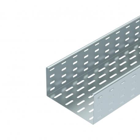


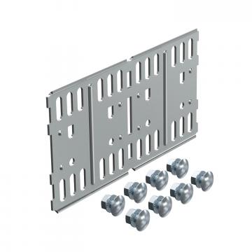 Straight and angle connector 110 FT
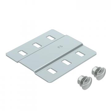 Joint plate DD
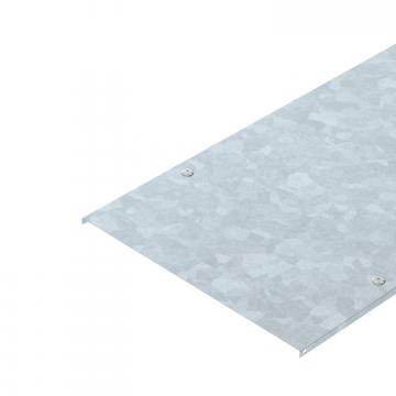 Cover with turn buckle FT
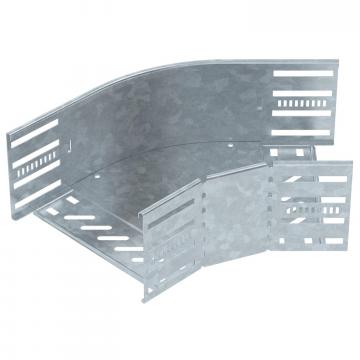 45° bend 110 FT
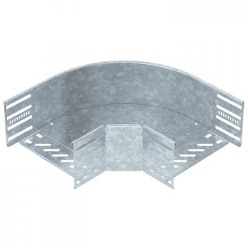 90° bend 110 FT
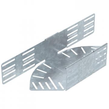 Bend, angle-adjustable, 110 FT
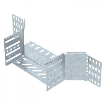 Add-on tee 110 FT
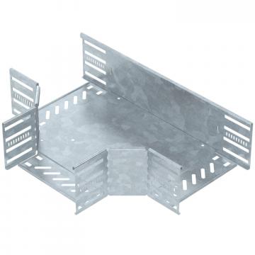 T piece 110 FT
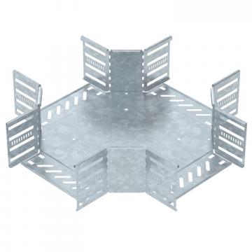 Cross-over 110 FT
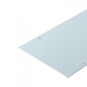 Cover with turn buckle DD
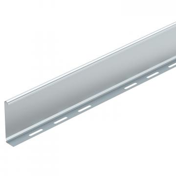 Barrier strip 110 DD
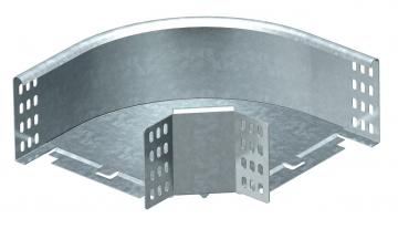 90° bend 110 FT